Figure 1.1 -- Structure of stack frame
Most of px is written in the PDP-11 assembly language, using the UNIX assembler as. Portions of px are also written in the UNIX systems programming language C. Px consists of a main procedure which reads in the interpreter code, a main interpreter loop which transfers successively to various code segments implementing the abstract machine operations and built-in procedures and functions, the code segments themselves, and a number of routines which support the implementation of the Pascal input-output environment.
The interpreter runs at a fraction of the speed of equivalent compiled C code, with this fraction varying from 1/5 to 1/15. The fact that the interpreter implements 32 bit integer arithmetic on a 16 bit machine notably degrades its speed. In a code generated Pascal for a PDP-11, 32 bit integers would be undesirable.
The interpreter occupies 14.6K bytes of instruction space, which is shared between all instances of the interpreter, and 5K bytes of data space of which there is a copy for each interpreter execution.
The interpreter occupies 14.6K bytes of instruction space, shared among all processes executing Pascal, and has 4.6K bytes of data space (constants, error messages, etc.) a copy of which is allocated to each executing process.
Px normally interprets the code left in an object file by a run of the Pascal translator pi. The file where the translator puts the object originally, and the most commonly interpreted file, is called obj. We will first describe the way the object file was prepared in version 1.0 of the interpreter.
In version 1.0 of the interpreter, the obj file has an extremely simple format. The first word of the file has the octal value 404, a ``magic'' number. This number, like the numbers 407, 410, and 411 which signify executable files to the system, can be recognized by a modified shell (command interpreter) which can then fork instances of px to interpret the file. In this way, Pascal objects can be referred to at the shell level by typing their names. The modified shell can open each file which is executable but does not have a magic number recognized by the operating system. If the first word of such a file is 404, then the shell recognizes the file as a Pascal object, and creates an instance of the Pascal interpreter with the specified file as its first argument. This, importantly, allows all processes executing Pascal objects to share the same interpreter, and allows the Pascal object files to be small as they do not contain a copy of the interpreter.
With version 1.1 of the Pascal system an option exists to have the translator prepare true executable files. In order that all persons using px share a common text image, this executable file is not an interpreter, but rather a small process which coordinates with the iinterpreter to start execution. The way in which this happens is somewhat complicated. When one of these object files is created, the interpreter code is placed at the end of a special ``header'' file and the size of the initialized data area of this header file is expanded to include this code. When the process executes, the interpreter code is thus available at a easily determined address in its data space. When executed, the object process creates an pipe , creates another process by doing a fork , and arranges that the resulting parent process becomes an instance of px . The child process then writes, through the pipe whicch it has to the parent, interpreter process, the interpreter code. When this process is complete, the child exits.
The real advantage of this approach is that it does not require modifications to the shell, and that the resultant objects are ``true objects'' not requiring special treatment. A simpler mechanism would be to determine the name of the file which was executed and pass this to the interpreter. However it is not possible to determine this name in all cases. *
After the first word containing the value 404, the remainder of the obj file contains the object code.
* For instance, if the pxref program is placed in the directory `/usr/bin' then when the user types ``pxref prog1.p'' the first argument to the program, nominally the programs name, is ``pxref.'' While it would be possible to search in the standard place, i.e. the current directory, and the system directories `/bin' and `/usr/bin' for a corresponding object file, this would be expensive and not guaranteed to succeed. Several shells exist which allow other directories to be searched for commands, and there is, in general, no way to determine what these directories are.
Pascal object code is relocatable as all addressing references for control transfers within the code are relative. The code consists of instructions interspersed with inline data. All instructions have a length which is an even number of bytes, that is, an integral number of words. No variables are kept in the object code area.
The first byte of a Pascal interpreter instruction contains an operation code. This allows a total of 256 major operation codes, and 219 of these are in use in the current px. The second byte of each interpreter instruction is called the ``sub-operation code'', or more commonly the subop. It contains a small integer which may, for example, be used as a block-structure level for the associated operation. If the instruction can take a fullword constant, this constant is often packed into the subop if it fits into 8 bits and is not zero. A subop value of 0 indicates that the constant wouldn't fit and therefore follows in the next word. This is a space optimization, the value of 0 for flagging the longer case being convenient because it is easy to test.
Other instruction formats are used. The branching instructions take an offset in the following word, operators which load constants onto the stack take arbitrarily long inline constant values, and a large number of operations deal exclusively with data on the interpreter stack, requiring no inline data.
The interpreter emulates a stack-structured Pascal machine. The ``load'' instructions put values onto the stack, where all arithmetic operations take place. The ``store'' instructions take values off the stack and place them in an address which is also contained on the stack. The only way to move data or to compute in the machine is with the stack.
To make the interpreter operations more powerful and to thereby increase the interpreter speed, the arithmetic operations in the interpreter are ``typed''. That is, length conversion of arithmetic values occurs when they are used in an operation. This eliminates the need for interpreter cycles for length conversion and the associated overhead. For example, when adding an integer which fits in one byte to one which requires four bytes to store, no ``conversion'' operators are required. The one byte integer is loaded onto the stack, followed by the four byte integer, and then an adding operator is used which has, implicit in its definition, the sizes of the arguments.
The interpreter deals with several different fundamental data types. In the memory of the machine, 1, 2, and 4 byte integers are supported, with only 2 and 4 byte integers being present on the stack. The interpreter always converts to 4 byte integers when there is a possibility of overflowing the shorter formats. This corresponds to the Pascal language definition of overflow in arithmetic operations which requires that the result be correct if all partial values lie within the bounds of the base integer type: 4 byte integer values.
Character constants are treated similarly to 1 byte integers for most purposes, as are Boolean values. All enumerated types are, in fact, treated as integer values of an appropriate length, usually 1 byte. The interpreter also has real numbers, occupying 8 bytes of storage, and sets and strings of varying length. The appropriate operations are included for each data type, such as set union and intersection and an operation to write a string which is on top of the stack to a file.
No special packed data formats are supported by the interpreter. The smallest unit of storage occupied by any variable is one byte. The built-ins pack and unpack thus degenerate to simple memory to memory transfers with no special processing.
The interpreter runtime environment uses a stack data area and a heap data area, which are kept at opposite ends of memory and grow towards each other. All global variables and variables local to procedures and functions are kept in the stack area. Dynamically allocated variables and buffers for input/output are allocated in the heap.
The addressing of block structured variables is accomplished through a fixed display which contains, for each statically active block, the address of its stack frame. *
This display is referenced by instructions which load and store variables and maintained by the operations for block entry and exit, and for non-local goto statements.
* Here ``block'' is being used to mean any procedure , function or the main program.
Three ``global'' variables in the interpreter, in addition to the ``display'', are the dp, lc, and the lp. The dp is a pointer to the display entry for the current block; the lc is the abstract machine location counter; and the lp is a register which holds the address of the main interpreter loop so that returning to the loop to fetch the next instruction is a fast operation.
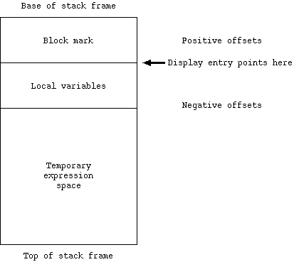
Each active block has a stack frame consisting of three parts: a block mark, local variables, and temporary storage for partially evaluated expressions. The stack in the interpreter grows from the high addresses in memory to the low addresses, so that those parts of the stack frame which are ``on the top'' of the stack have the most negative offsets from the display entry for the block. The major parts of the stack frame are represented in Figure 1.1.
Figure 1.1 -- Structure of stack frame
Note that the local variables of each block have negative offsets from the corresponding display entry, the ``first'' local variable having offset `-2'.
The block mark contains the saved information necessary to restore the environment when the current block exits. It consists of two parts. The first and top-most part is saved by the CALL instruction in the interpreter. This information is not present for the main program as it is never ``called''. The second part of the block mark is created by the BEG begin block operator which also allocates and clears the local variable storage. The format of these blocks is represented in Figure 1.2.
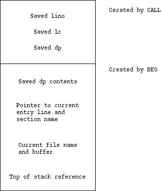
Figure 1.2 -- Block mark structure
The data saved by the CALL operator includes the line number lino of the point of call, which is printed if the program execution terminates abnormally; the location counter lc giving the return address; and the current display entry address dp at the time of call.
The BEG begin operator saves the previous display contents at the level of this block, so that the display can be restored on block exit. A pointer to 10 bytes of information giving the first eight characters of the name of this block and its beginning line number is also saved. This information is stored in the intepretor object code in-line after the BEG operator. It is used in printing a post-mortem backtrace. The saved file name and buffer reference are necessary because of the input/output structure (this is discussed in detail in sections 3.3 and 3.4). The top of stack reference gives the value the stack pointer should have when there are no expression temporaries on the stack. It is used for a consistency check in the LINO line number operators in the interpreter, which occurs before each statement executed. This helps to catch bugs in the interpreter, which often manifest themselves by leaving the stack non-empty between statements.
Note that there is no explicit static link here. Thus to set up the display correctly after a non-local goto statement one must ``unwind'' through all the block marks on the stack to rebuild the display.
A function returns its value into a space reserved by the calling block. Arguments to a function are placed on top of this return area. For both procedure and function calls, arguments are placed at the end of the expression evaluation area of the caller. When a function completes, expression evaluation can continue after popping the arguments to the function off the stack, exactly as if the function value had been ``loaded''. The arguments to a procedure are also popped off the stack by the caller after its execution terminates.
As a simple example consider the following stack structure for a call to a function f, of the form ``f(a)''.
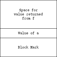
Figure 1.3 -- Stack structure on function call `f(a)'
If we suppose that f returns a real and that a is an integer, the calling sequence for this function would be:
PUSH	-8
RV4	a
CALL	f
POP	4
Here we use the operator PUSH to clear space for the return value, load a on the stack with an ``rvalue'' operator, call the function, pop off the argument a , and can then complete evaluation of the containing expression. The operations used here will be explained in section 2.
If the function f were given by
 10 function f(i: integer): real;
 11 begin
 12     f := i
 13 end;
then f would have code sequence:
BEG	0
	"f"
	11
LV	l,20
RV4	l,16
AS48
END
Here the BEG operator takes 12 bytes of inline data. The first word indicates the amount of local variable storage, here none. The succeeding two lines give the name of the block and the line number of the begin for error traceback. The BEG operator places a pointer to the name and line number in the block mark.
The body of the function here involved taking an address of the function result variable f using the address of operator LV . a . The next operation in the interpretation of this function is the loading of the value of i . I is at the level of the function f , here symbolically l, and the first variable in the local variable area.
The function completes by assigning the 4 byte integer on the stack to the 8 byte return location, hence the AS48 assignment operator, and then uses the END operator to exit the current block.
We can now describe the main interpreter loop. It is actually quite short:
loop:
	movb	(lc)+,r0
	add	r0,r0
	movb	(lc)+,r3
	jmp	*optab(r0)
First the main operation code is extracted from the first byte of the instruction. The code will be a small integer in the range -128 to 127. It is then doubled to make a word index into the operation table. Note that the sub-operation code is placed in register 3, and is thus available for use by the individual operation sequences. The hardware also leaves the condition codes set based on the value of this subop. The code will be discussed in section 2.1.
The label optab is in the middle of a branch table which has one operation address per word. The table is generated automatically from an abstract machine instruction list. The address of the instruction at loop is always contained in the register variable lp so that a return to the main interpreter loop both is quick and occupies little space. The return is thus a ``jmp (lp)'' instruction, defined for mnemonic value as the operator ``return'' in the intepreter, i.e.
return = 115
so that one can write the mnemonic ``return'' at the end of an interpreter code sequence.
Errors during interpretation cause a subroutine call to an error routine in a conventional fashion. An earlier version of the interpreter more compactly represented the raising of these conditions by using emulator traps (EMTs), a form of system call otherwise unused by UNIX. Errors were assigned small integer numbers and then referred to symbolically in the interpreter. The UNIX assember, as , provides a mechanism for defining the opcode ``error'' to be an ``emt,'' i.e.:
error = 104000 ^ sys
Thus there were many lines like
error ESTKOVFLO
in the interpreter. These cause a process fault, which is trapped by the system and passed to the label onemt in the interpreter which fetches the error code byte from the EMT instruction and calls the procedure error with this argument. Error processes the error condition, printing an appropriate error message and, usually, a backtrace.
In order that the interpreter run on a standard UNIX without using non-standard system calls to fetch the EMT code when running in separated instruction and data spaces, the current version of the interpreter places the error code in a global variable, before doing an EMT . Thus the EMT is used to compactly transfer control, but not for argument transmission.